Creating Exposed Trusses in Home Designer Pro
The information in this article applies to:

QUESTION
In Home Designer Pro, how can I create exposed roof trusses in a room with a cathedral ceiling?
ANSWER
When a roof truss is drawn in Home Designer Pro, the program locates a roof plane to define the top chords of the truss, and a ceiling plane to define the location of the bottom chord. You can create exposed trusses by creating a ceiling to define where you want the trusses' bottom chords, drawing the trusses, and then removing the ceiling.
To set up the structure
-
Open
 the plan file in which you would like to create exposed roof trusses.
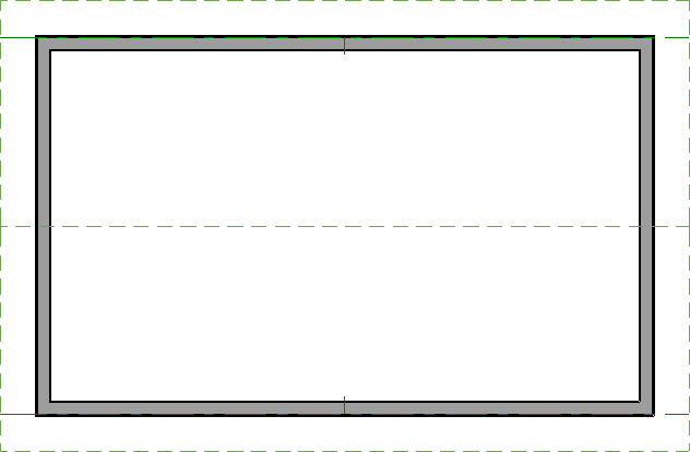
- In this example, a simple rectangular structure with a gable roof is used.
- If your plan has multiple floors, go to the floor where you want to create exposed trusses.
- In this example, a simple rectangular structure with a gable roof is used.
- Using the Select Objects
 tool, click in the center of the room to highlight it, then click the Open Object
  edit button.
- On the Structure panel of the Room Specification dialog that opens, set the Rough Ceiling height to the height for the wall top plates, then click OK.
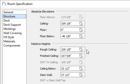
If all rooms on this floor have the same plate height, it is best to set the Rough Ceiling value in the Floor Defaults.
- Next, select Edit> Default Settings
 , select the Framing category, then click Edit.
- On the Trusses panel of the Framing Defaults dialog, specify the desired Member Depth and Maximum Horizontal Span properties, then click OK and Done to close the dialogs.
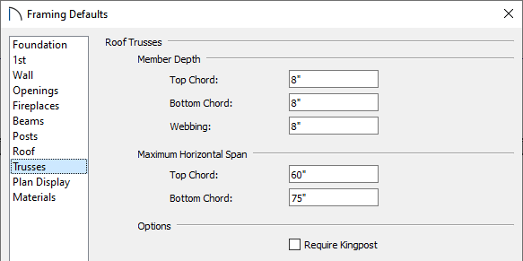
In this example, the Depth values are set at 8" and the Span values are unchanged.
- Select Build> Roof> Build Roof
 and on the Roof panel of the Build Roof dialog that opens:
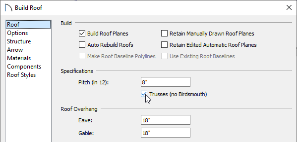
- Check Build Roof Planes
- Uncheck Auto Rebuild Roofs.
- Specify the desired Pitch (in 12).
- Check Trusses (no Birdsmouth).
- Click OK to close the dialog and build the roof.
- Check Build Roof Planes
- Ceiling modifications may need to be made before generating your trusses. For example:
- Use the default flat ceiling if you want to produce standard trusses.
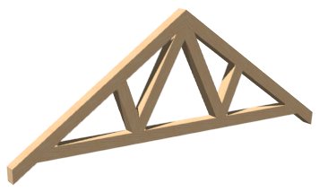
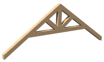
- Raise the ceiling height of a room if you'd like to create trusses with a raised bottom chord (make a note of the original value before doing so).
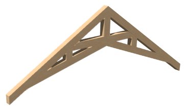
- Remove the default flat ceiling and draw sloped Ceiling Planes if you'd like to produce scissor trusses. More on creating scissor trusses can be found in the Related Articles section below.
- Use the default flat ceiling if you want to produce standard trusses.
To draw and replicate the trusses
- Select Build> Framing> Roof Truss
 from the menu, then click and drag a line over the roof to create a single roof truss.
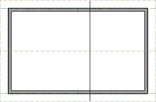
Note: If you receive a Question dialog stating that "The layer "Framing, Roof Trusses" is not displayed. Do you want to turn on the display of this layer in the current view?", click yes.
- Using the Select Objects
 tool, select the newly created truss and click the Open Object
  edit button.
- In the Roof Truss Specification dialog that opens:
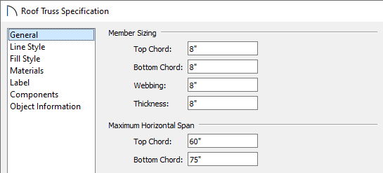
- On the General panel, specify the Thickness.
In this example, an 8" thickness is specified to match the member properties set in the section above.
- On the Materials panel, specify your desired material for the truss.
- Click OK once all desired changes have been made.
- On the General panel, specify the Thickness.
- Next, move the truss into position over a non-bearing wall by either using its edit handles or by using a dimension line.
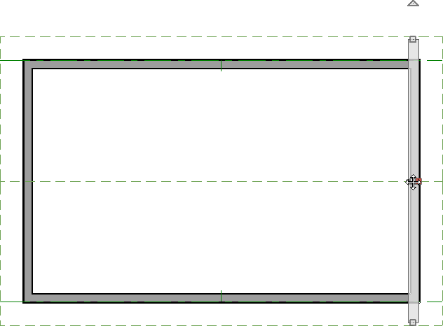
- With the first truss in place over an exterior wall, click on it to select it, then click the Transform/Replicate Object
 edit button to make copies of the truss.
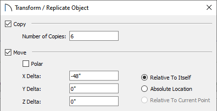
- Check the box beside Copy and specify the number of copies that you want to create.
- Check the box beside Move and specify the move interval for each copy made, as well as along what axis.
A negative value in the X Delta field will copy the trusses left, while a positive value will copy the trusses right.
A negative value in the Y Delta field will copy the trusses down the screen, while a positive value will copy the trusses up the screen.
- Check the box beside Copy and specify the number of copies that you want to create.
- You may find that you need to adjust the position of the last replicated truss to agree with your particular structure.
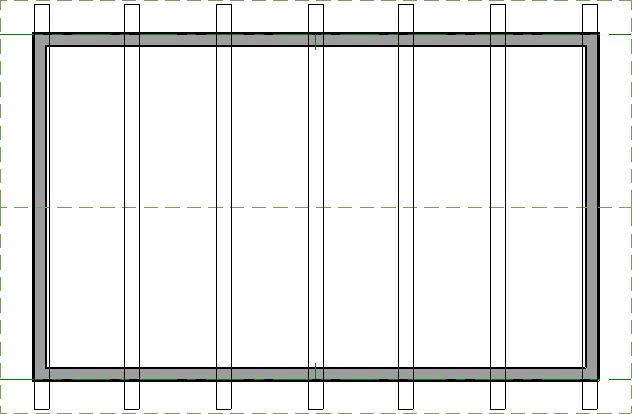
Once the trusses are placed, you may want to specify certain trusses to be end trusses. To do this, select the end trusses, open them up to specification, then check the "End Truss" box located in the Roof Truss Specification dialog.
To make the trusses exposed
- When your trusses are in place, use the Select Objects
 tool to select the room once again, then click the Open Object
  edit button.
- In the Room Specification dialog that opens:
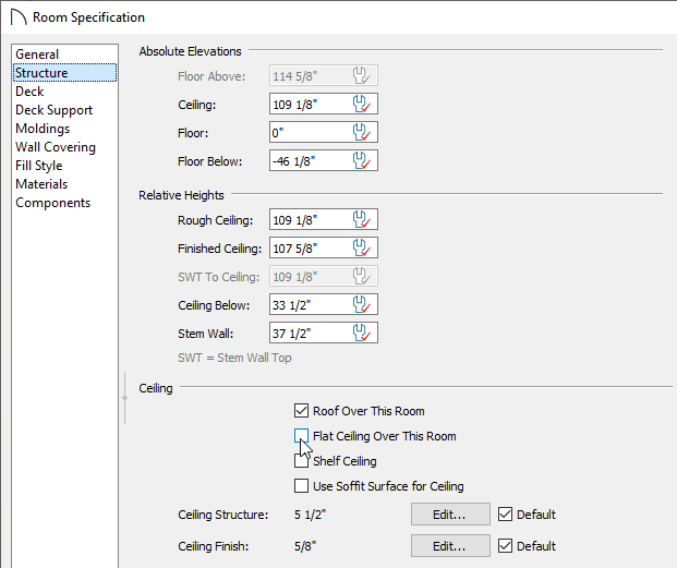
- On the Structure panel, uncheck the box beside Flat Ceiling Over This Room.
- If you changed the Ceiling height value to produce a modified truss (mentioned in Step 7 of the first section of this article), you may want to restore the previous value at this time.
- Click Edit next to Ceiling Finish if you'd like to change the thickness of the ceiling material.
- On the Materials panel, select the Ceiling Finish component, then click the Select Material button to choose your desired ceiling material.
- Click OK once you have chosen a material, then click OK again to apply your changes.
- On the Structure panel, uncheck the box beside Flat Ceiling Over This Room.
- Select 3D> Create Perspective View> Full Camera
 from the menu, then click and drag a camera arrow inside the room where the trusses are.
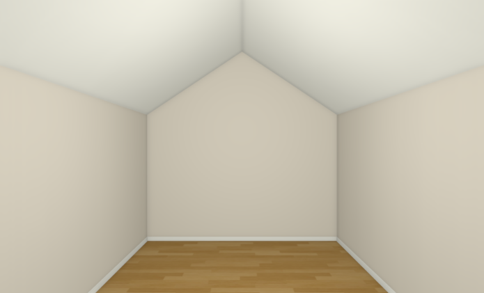
- With the 3D camera view active, select Tools> Display Options
 from the menu.
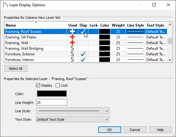
- In the Layer Display Options dialog, place a check in the Disp column or Display checkbox for the "Framing, Roof Trusses" layer, then click OK.
Your camera view may now look similar to the image below.
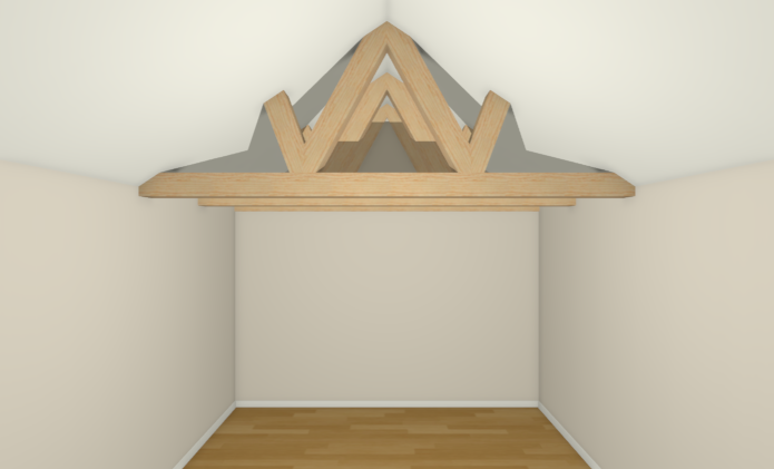
- If you would like the top chords of your trusses to be exposed, click on the roof planes above to select them, then click Open Object
 edit button.
Note: You can group select multiple roof planes by holding down the Shift key on your keyboard, then clicking on each roof plane. For more information on group selecting objects, please see the Related Articles section below.
- In the Roof Plane Specification dialog that displays:
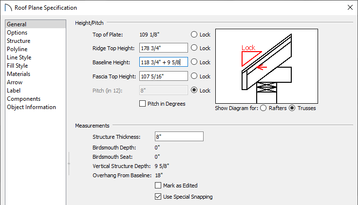
- On the General panel, lock the pitch by clicking the radio button to the right of the Pitch (in 12) text field, then increase the Baseline Height value.
In this example, the Baseline Height value was increased by 9 5/8". If your ceiling finish is a material other than drywall, such as tongue and groove for example, you may want to adjust this value accordingly.
- Click OK to close the dialog and apply the change.
Your camera view may now look similar to the image below if you have chosen to display the top chords of your trusses.

Your exposed trusses are now in place. If you would like to make additional changes to the roof's structure, consider following the optional steps below.
- On the General panel, lock the pitch by clicking the radio button to the right of the Pitch (in 12) text field, then increase the Baseline Height value.
- Navigate to Build> Framing> Build Framing
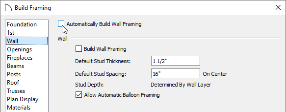
 , and on the Wall panel of the Build Framing dialog, uncheck Automatically Build Wall Framing, then click OK.
-
Open
 the roof planes up to specification once more, and on the Structure panel, change the Rafter Depth, along with any other roof properties to your liking.
If the rafter depth is changed prior to turning off automatic wall framing, your wall top plates may conflict with the exposed trusses. It's best to only perform this step after your walls are in place and the wall framing is complete.
Specifying a rafter depth value of 0" will allow the surface layers of the roof to sit directly on the trusses.