Creating a Retaining Wall
Reference Number:
KB-00990
Last Modified:
November 14, 2023
This article also applies to the following legacy products:
Pro | Architectural | Suite
Pro | Architectural | Suite
QUESTION
I have sloped terrain in my plan and need to hold it back with a wall. How can I do this?

ANSWER
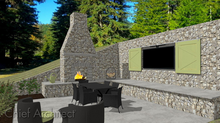
Use the Retaining Wall tool to easily place retaining walls in your terrain. Retaining walls are automatically drawn with footings and a terrain break, which creates a sharp drop in the terrain along the wall.
To create a retaining wall
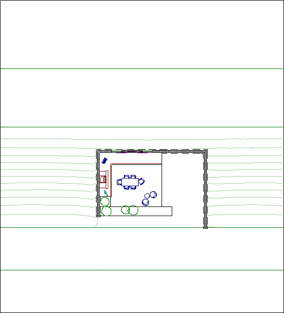
- To add a retaining wall, your plan must first have a terrain perimeter. You can add a terrain perimeter quickly and easily by selecting Terrain> Create Terrain Perimeter
 from the menu.
- If you have just created your terrain perimeter, you will likely not have any elevation data placed, and if you insert a retaining wall into flat terrain, it will look like a concrete strip in 3D camera views.
- The height of the retaining wall is determined by the elevation on each side.
- By default, the retaining wall will follow the elevation of the terrain - cutting at the apex and the bottom.
- The height of the retaining wall is determined by the elevation on each side.
- Select Terrain> Elevation Data> Elevation Line
 and draw several elevation lines.
Note: An elevation line drawn near the end of another will cause them to merge.
- Now that we have placed some elevation lines, use the Select Objects
 tool to select an elevation line, then click on the Open Object
  edit button to open it for specification.
Values entered are in inches, unless the foot (') mark is added. Negative values should be preceded with a hyphen (-).
- Once you have set the appropriate values for your elevation line, click OK to confirm the changes and close the dialog.
- With the terrain perimeter created and the elevation lines set, navigate to Terrain> Terrain Wall and Curb> Straight Retaining Wall
 , then click-and-drag to create a retaining wall.
- Select Terrain> Build Terrain
 to rebuild the terrain, and notice that the elevation lines are above and below the walls. No elevation lines are between the walls.

- Lastly, create a Camera
 view to see the results.
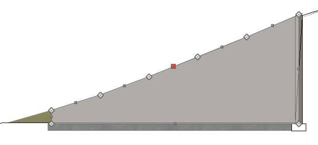
In Home Designer Pro, a retaining wall's height can be specified independent of the terrain by selecting and editing the wall in a cross section/elevation view.
To change the height of a retaining wall in Home Designer Pro
- Select 3D> Create Orthographic View> Cross Section/Elevation
 , then click-and-drag the camera toward the retaining wall to create a cross section/elevation view of the retaining wall.
Note: While a retaining wall can be edited in any 3D view, adjusting the height is often easiest and most accurately done in a Cross Section/Elevation view.
- Click on the wall near the top edge to select it, then use the edit handles that display to adjust the wall to your liking.

- If diamond edit handles exist along the top edge of the wall, the wall may have a slight curve, which can be adjusted further to your liking.
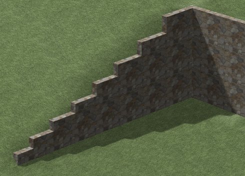
You can also use the Add Break edit tool to place diamond edit handles (break points). This can be useful if you're wanting to create a stepped retaining wall, like shown in the image below.

Related Articles