Creating a Plot Plan in Home Designer Pro
The information in this article applies to:

QUESTION
How do I create a plot plan in Home Designer Pro?
ANSWER
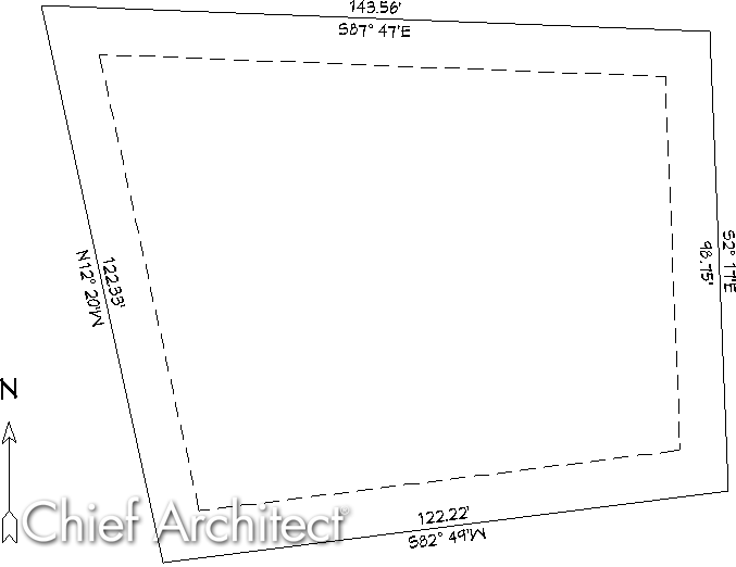
A plot plan can easily be created in Home Designer Pro using the Input line tool and modifying the resulting polyline to display length and bearing information. Setback lines can also be created and customized.
To begin creating a plot plan
- Launch Home Designer Pro, and navigate to File> New Plan
 .
.
- Select CAD> Lines> North Pointer
 , then click and drag a north arrow straight up in your floor plan view.

- Select CAD> Lines> Input Line
 to display the New CAD Line dialog.
- In the New CAD Line dialog, click on the Number Style button to display the Dialog Number/Angle Style dialog.
Note: These settings only apply to numbers displayed in the specification dialogs and status bar. They do NOT apply to objects that display in plan and other view windows.
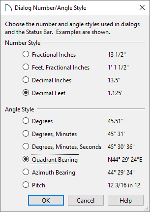
- Under Number Style, move the radio button to Decimal Feet.
- Under Angle Style, move the radio button to Quadrant Bearing.
You can also choose Azimuth Bearing if you desire.
- Click OK.
- Under Number Style, move the radio button to Decimal Feet.
- In the End Point section of the New CAD Line dialog:
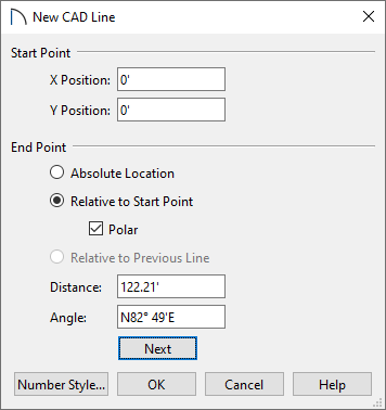
- The X and Y Position is the start point for the first line of the property that will be drawn.
By default, this will be set to 0 for both, unless you placed a CAD point in the plan prior to opening this dialog.
- Click the radio button beside Relative to Start Point.
-
- Check the Polar box.
- The X and Y Position is the start point for the first line of the property that will be drawn.
- Enter the listed information to define the property. Once one line is specified, click the Next button, then enter the values listed on the following line. Proceed until each edge of the property is defined.
- Distance = 122.21', Angle = N82° 49'E
- Distance = 98.75', Angle = N2° 17'W
- Distance = 143.56', Angle = N87° 47'W
- Distance = 122.33', Angle = S12° 20'E
The above coordinates serve as an example only. Use these coordinates to learn how to create a plot plan. Once you understand the process, you can substitute in your own coordinates.
- Click OK after entering in the last value to close the dialog and return to floor plan view, where we can see the polyline we created.
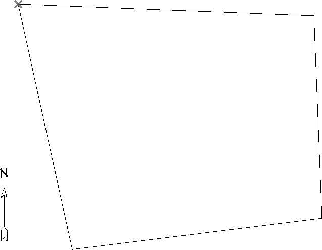
Straight property lines can also be converted to curved property lines by selecting the desired edge and clicking on the Change Line/Arc edit button.
- Next, use the Select Objects
 tool to select the polyline you created, and click on the Open Object
  edit button.
- On the Line Style panel of the Polyline Specification dialog that opens, check the Show Length and Show Angle boxes, then click OK to return to your floor plan view.
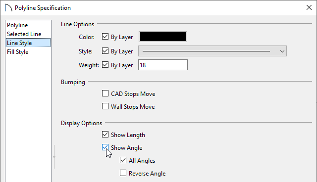
Note that it defaults to having lengths of inches and angles in regular degrees. Most property lines are shown in bearings and decimal feet.
To change the display to decimal feet and bearings
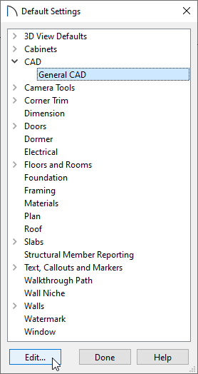
- Select Edit> Default Settings
 .
.
- Expand the CAD category, select General CAD, then click Edit.
- In the CAD Defaults dialog:
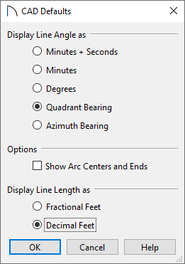
- Under Display Line Angle as, select Quadrant Bearing.
You can also choose Azimuth Bearing if you desire.
- Under Display Line Length as, move the radio button to Decimal Feet.
- Click OK.
- Under Display Line Angle as, select Quadrant Bearing.
- To adjust the size of the Length and Angle displayed on your plot plan polyline, stay within the Default Settings, expand the Text, Callouts and Markers category, select Text Styles, then click Edit.
- Select the Plot Plan Text Style, then click Edit.
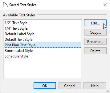
- In the Text Style Defaults dialog that displays next, specify your desired value in the Character Height field.
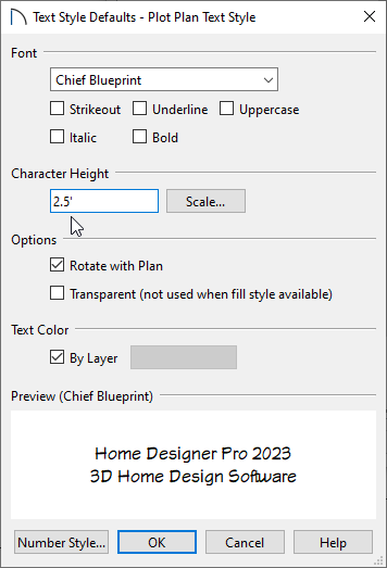
Note: Other properties relating to the Length and Angle text can be adjusted here, such as the Font style and formatting characteristics.
- Click OK, OK, and Done to close out of all of the dialog boxes.
- Next, select Tools> Display Options
 .
.
-
Locate and select the "CAD, Default layer," use the Text Style drop-down menu to select the Plot Plan Text Style, then click OK.
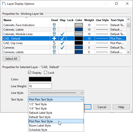
The plot plan polyline should now look similar to the image below.
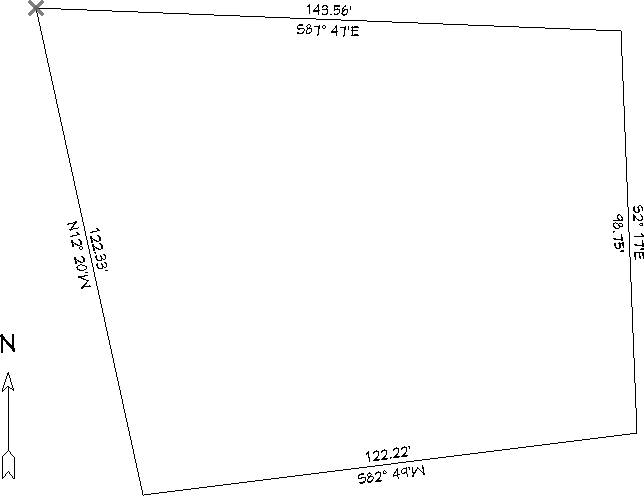
If you want to add details such as the property offset, now is the time to make these changes.
To create setback lines
- Select Edit> Preferences
 from the menu if you're on a Windows PC or Home Designer> Preferences
  if you're on a Mac.
- On the Behaviors panel, Under Edit Type, move the radio button to Concentric, then in the Jump field, type in the setback distance required by your local planning department.
In this example, a value of 10' is specified.
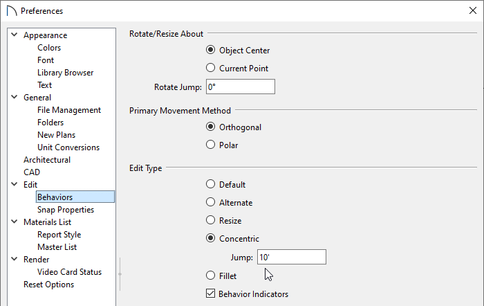
- Click OK to close the dialog and return to a floor plan view.
- Using the Select Objects
 tool, click on the plot plan polyline to select it, then navigate to Edit> Copy and Paste in Place
  from the menu.
- Place your cursor over a corner edit handle, then click and drag towards the center of the polyline until a copy of the polyline appears inside. Each edge of the inner polyline will be 10' apart from the outside polyline.
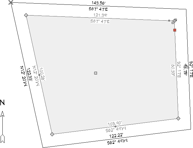
- Select the inner polyline and click the Open Object
 edit button.
- On the Line Style panel, select a dashed line style from the drop-down list, uncheck Show Length and Show Angle, then click OK.
- When you have finished creating the setback lines, select Edit> Edit Behaviors> Default
 to restore the default edit behavior.
- Finally, select CAD> Points> Delete Temporary Points
 to remove any temporary points.
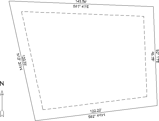
To view the plot perimeter in 3D
- Using the Select Objects
 tool, click on one of the outer polyline's edges to select it.
- With the polyline selected, click on the Convert Polyline
 edit button.
- In the Convert Polyline dialog that appears, select the Terrain Perimeter radio button, then click OK.
Note: If the Terrain Perimeter option is grayed out and inaccessible, a terrain perimeter may already exist in the plan or the plot plan polyline is not fully enclosed.

- In the Terrain Specification dialog that appears next, make sure that everything is setup to your liking, then click OK.
- Lastly, create a Camera
 view to see the results.
You can now add elevation information to adjust the slope of the plot, if required, using the various Terrain tools.